- Products
-
Liquid Distributors
-
Liquid Distributors
-
Liquid Distributors
-
Packed Tower Internals
-
Packed Tower Internals
-
Packed Tower Internals
Liquid Distributors
THE BEST PARTNER HANBIT SOLTECH


Hanbit Soltech Corporation defines two categories of liquid distributors based on our proprietary quantitative distributor rating system.

- • High Performance Liquid Distributor
- more than 90% quality
- • Traditional Performance Liquid Distributor
- generally 40% - 85% quality
Conversely, a tower with fewer stages of traditional packing (Pall rings, Saddles, Raschig rings, etc...) is less sensitive to distribution quality. This tower permits the use of a less expensive traditional distributor.
Hanbit Soltech Corporation has established the minimum recommended guidelines for the drip point density on the liquid distributor as shown below.
- • Distribution Point Density, pts/㎡
- 60-80
- 80-100
- 100-120
- • Structured Packing, ㎡/㎥
- <250
- 250-350
- >350 & Wire Gauze Packing
- • Random Packing, ㎡/㎥
- <210
- 210-300
- >300
Distribution Orifice Sizing
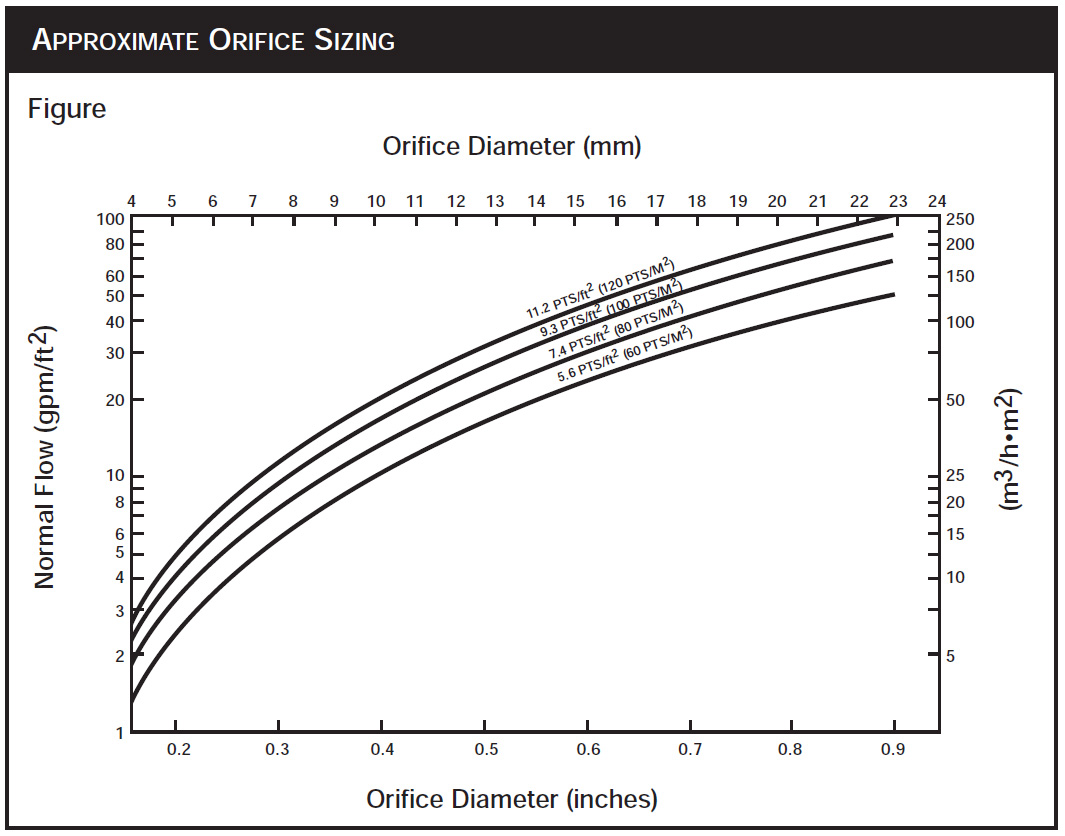
The approximate orifice size is indicated in figure provided the distributor with an operating range of 60 to 120% of the design flow and this applies to gravity-fed distributors with fixed minimum liquid head.
We generally design to have a maximum flow variation, defined as the coefficient of variation(Cv), equal to no more than 5% at design rate and no more than 10% at turndown rates. Special designs of distributor can be made for processes requiring lower flow variations. Designs of better than ± 3% at 100% design rate and better than ± 5% at a 2:1 turndown are feasible.
Fouling
V-notch weir or side wall orifices are generally less prone to plugging than orifices in the bottom of a distributor, but distributors designed with V-notch weirs may have flow variation outside the high performance range. Distributors with bottom orifices are not normally recommended for orifice sizes of 6 mm or less when the fouling tendency is expected.
The followings are the fouling resistance of the various metering arrangements.
• “V” notch weir
• Slotted weir
• Side wall orifice with orifice strainer
• Side wall orifice
• Bottom orifice with orifice strainer
• Bottom orifice
Model HPD-106/107
Pan Distributor/Redistributor
Orifices in the pan bottom are arranged to provide optimum distribution quality together with gas risers set between the orifices. When used for higher flow rates, this distributor will have large orifices that will not tend to foul. For lower flow rates, orifice strainer caps or the Model HCD-136/137 should be considered if the system is fouling. The standard turndown range is 2:1.
• Column diameters : 250 to 900 mm
• Liquid rates : above 5 m3/hr/m2
• Orifices in pan base
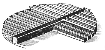
Model HDD-116/117
Deck Distributor/Redistributor
The deck-type construction allows good liquid cross-flow between gas risers to be set between orifices in deck specifically spaced for a high distribution quality. As this deck distributor normally handles higher liquid flow rates, the orifices are usually large and allow moderate fouling resistance. The standard turndown range is 2:1.
• Column diameters : greater than 900 mm
• Liquid rates : above 30 m3/hr/m2
• Orifices in deck
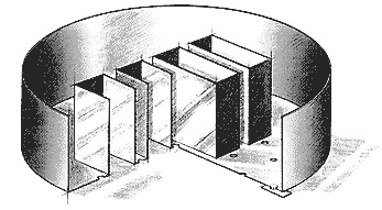
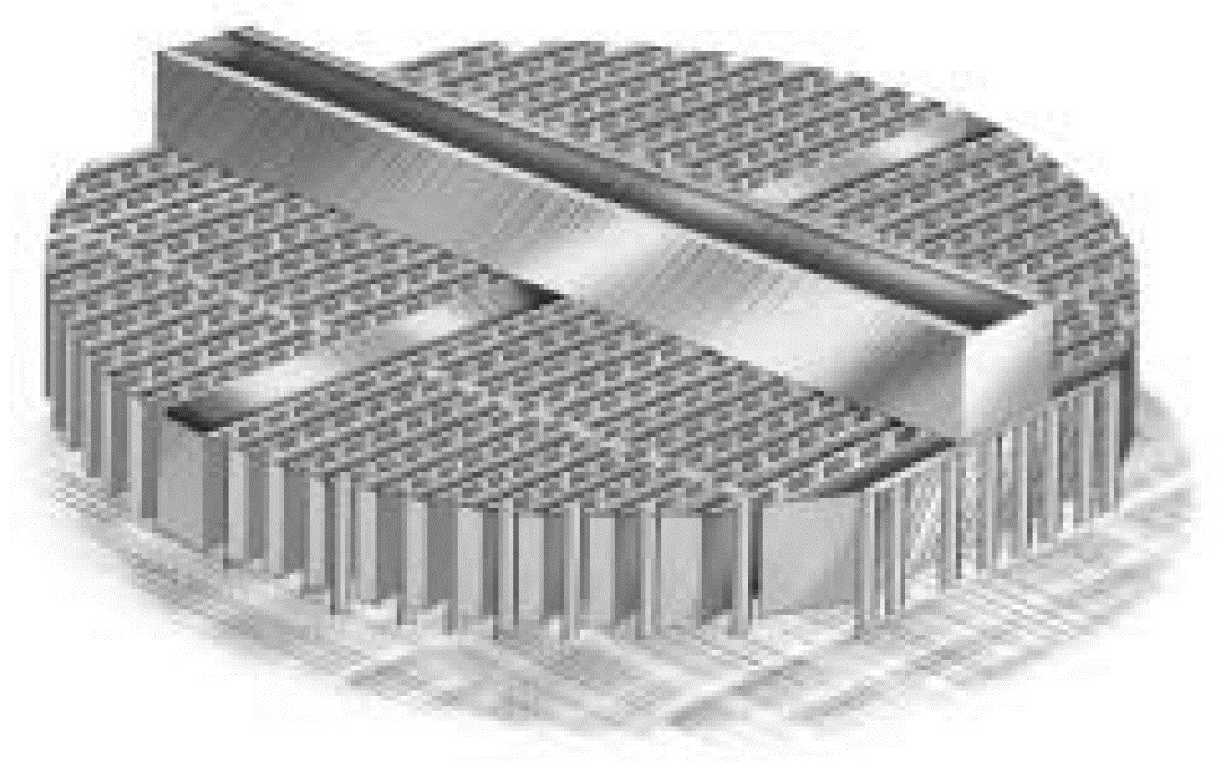
Model HCD-126/127
Channel-Type Trough Distributor/Redistributor
Orifices in the channel base are placed to optimize distribution quality. The main channel is connected to the distribution channels directly. The liquid flow in all the channels of the distributor is hydraulically connected to each other. The vapor passage is provided by the space between the channels. The channel-type construction allows minimal leakage due to few joints and easy distributor leveling, which is critical in large diameter towers. The standard turndown range is 2:1.
• Column diameters : greater than 900 mm
• Liquid rates : 5 - 40 m3/hr/m2
• Orifices in channel base
Model HCD-136/137
Channel-Type Trough Distributor/Redistributor
Orifices in the side-wall of the channels are placed to optimize distribution quality. The liquid from each discharge point is conducted into the lower vapor velocity region below the distributor troughs. This results in low entrainment levels. The resistance to fouling of this distributor is higher than that of deck-type distributors because it features a debris collection zone below the side-wall orifices. The main channel provides structural support as well as equalization of liquid between channels. The standard turndown for a single side-wall orifice is 2:1. However, the turndown range can be extended by using two or three orifices at different levels of the same discharge point. Turndown ratios up to 10:1 are achievable.

• Column diameters : greater than 250 mm
• Liquid rates : 0.75 - 30 m3/hr/m2
• Side-wall orifices
Model HTD-156
Trough Distributor
Orifices in the side-wall of the troughs are placed to issue liquid against an splash baffle that greatly multiply into many more drip points before the liquid is released onto the packing. Since this multiplying effect gives more drip points even at the low point density, the side-wall orifices can be designed as large as possible for fouling resistance. This trough distributor with baffle has good distribution characteristics particularly at low liquid rates.

• Column diameters : greater than 760 mm
• Liquid rates : 0.5 - 20 m3/hr/m2
• Side-wall orifices with splash baffle
Model HTD-186
Trough Distributor
The Model HTD-186 trough distributor is similar to the Model HCD-136 channel distributor, however, the Model HTD-186 uses a parting box over the distribution troughs instead of a center channel at the same level as the lateral troughs for the crossflow. Therefore, this distributor requires more column height, but it is easier to seal and requires no gasket. Because of no center channel for the crossflow, the parting box design is crucial to this distributor performance.
• Column diameters : greater than 900 mm
• Liquid rates : 0.75 - 20 m3/hr/m2
• Side-wall orifices
Model TPD-798
Pan Distributor
The Model TPD-798 “Weir-Riser” distributor is used for highly fouling services in towers less than 1200 mm ID. Cylindrical risers with “V” notched weirs are used as liquid downcomers. This distributor effectively handles a wide turndown range due to the weirs, which permit greater flow as the liquid head increases. However, maximum liquid flow is limited by the gas flow since they are flowing counter-currently in the same passages.
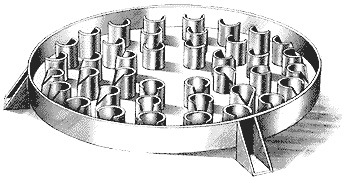
• Column diameters : 300 to 1200 mm
• Liquid rates : 2.5 - 20 m3/hr/m2
• Weir in risers
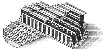
Model TTD-806
Trough Distributor
The Model TTD-806 “Weir-Trough” distributor is the most versatile distributor and it incorporates a compound weir design that enables it to handle effectively a wide range of liquid flow requirements. It is particularly effective in large towers when large volumes of gas and liquid are handled. It is also quite resistant to fouling and can handle large volumes of suspended solids in the liquid. Liquid is metered to the closed-end troughs by one or more parting boxes and overflows by gravity through the weirs of the troughs. The number of parting boxes depends on the tower diameter and liquid flow rate. The standard turndown ratio is 2.5:1, but higher turndown ratios can be achieved with special parting box design.
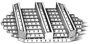
• Column diameters : greater than 900 mm
• Liquid rates : 5 - 100 m3/hr/m2
• Weirs in troughs
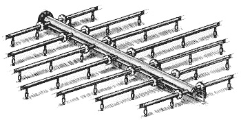
Model PAD-844
Pipe-Arm Distributor
The Model PAD-844 ladder pipe distributor is made of a series of pipes with orifices in the bottom of the pipes for distribution. This ladder-type distributor requires little column elevation to accomplish its distribution task, and it provides high open area for high vapor flow. It is designed primarily for use where feed liquid under pressure is available. It is sometimes used in towers where low residence time is required, such as where polymerization can occur. The Model PAD-844 should be used only with clean liquids. The normal turndown ratio is 2.5:1.

• Column diameters : greater than 430 mm
• Liquid rates : 4 - 25 m3/hr/m2
• Orifices in the bottom of the pipes
Model SND-1044
Spray Nozzle Distributor
The Model SND-1044 spray-type distributor is constructed of a header pipe and laterals that supply liquid to a pattern of spray nozzles. Full cone spray nozzles with an angle of 90° or 120° are the standard design for most applications. This spray distributor can be designed for very low liquid rates because each spray nozzle covers a large area of the tower. Fouling or plugging can be a concern with spray nozzles. The number of sprays per square meter of the cross sectional area is much smaller than the number of drip points in a gravity distributor. This permits larger spray nozzle openings compared to gravity distributors, which reduces their plugging tendency. The normal turndown ratio is limited to 2:1 by the range of effective operation of the spray nozzles.
• Column diameters : no restrictions
• Liquid rates : 0.5 - 120 m3/hr/m2
• Spray nozzles