- Products
-
Tray Design and Construction
-
Tray Design and Construction
-
Tray Design and Construction
-
Fractionation Trays
-
Fractionation Trays
-
Fractionation Trays
Tray Design and Construction
THE BEST PARTNER HANBIT SOLTECH
Tray Design and Construction
Tray tower internals are generally (but not always) removable items of tower hardware provided to achieve a process effect. These include not only trays, but also de-entrainment devices, impingement plates, baffles, pipes, internal sumps, etc. Hanbit Soltech Corporation designs the attachments such as the tray support rings, the downcomer clamping (or bolting) bars, beam seats and beam clips that hold the trays.

Tower Attachments
Tower attachments are permanent items of tower hardware welded to the vessel, generally by the vessel fabricator. There are internal and external attachments. Internal attachments including support rings, bolting and clamping bars, beam seats, clips and brackets, are provided to support and/or secure various tower internals by the vessel fabricator.Top Installable (Removable)
Trays are top installable, or top removable, if they are designed to be installed from the bottom up and removed from the top down, and the people doing most (but not necessarily all) of the installation or removal work are located above the tray being installed or removed. Bottom installed trays are normally used only for special situations, such as when traying is to proceed rapidly in both directions from tower manholes located at the top and bottom of the column, or in situations where trays are expected to sustain damage, and repair or replacement is more easily done from below.Tray Manway
A manway permits workman passage through equipment partitions. A tray manway is a removable panel section in the fractionating tray which provides an opening through the deck allowing passage to adjacent sections within the column tray spacings for maintenance and inspection.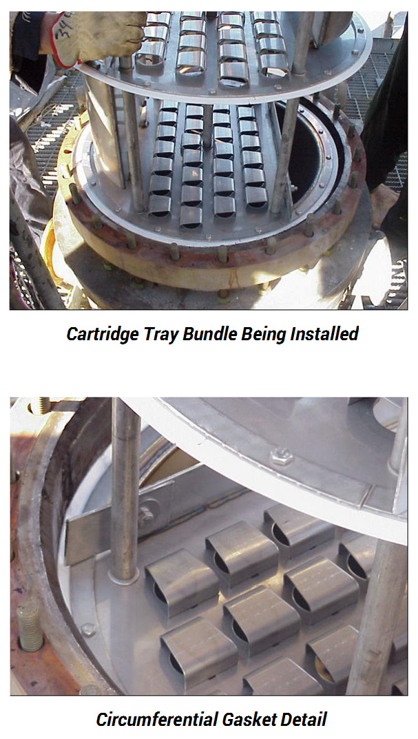
Cartridge Tray
Cartridge trays are widely used in columns too small for normal sectional tray installation and maintenance. This is generally considered to be 3 feet (0.91 m) in diameter or less. Packing is usually the preferred choice for these small diameter columns, but there are several reasons why trays would be advantageous. Examples include fouling systems, certain foaming systems, high pressure applications, and systems that require a large turndown.Cartridge trays consist of a series of trays pre-assembled in a bundle. The number of trays contained in a bundle varies with tower diameter. Larger diameter bundles may only have 4-5 trays, whereas smaller diameter bundles may have 8-10 trays. The reason for the difference is the increased frictional resistance generated during installation between the tower shell and the bundle for larger diameter bundles. The trays themselves can be of any type: sieve, valve, bubble cap, dual flow, etc.
The tray decks are connected together by tie-rods that run the length of the bundle. Spacer rods are inserted over the tie-rods to ensure the correct tray spacing. The bundle is bolted at the ends to make a complete unit that is inserted through a body flange into the column. The bundles can be bolted together as they are installed so that all the trays in a section of column are connected together. The bundles rest on support clips welded to the shell at the bottom of a column section.
The downcomers are envelope-style and are integral to the tray deck. The trays are sealed to the column wall by circumferential gaskets.
Slot-and-Tap Design Construction
Hanbit Soltech Corporation can design without bolting at the panel-to-panel connection that can help to improve the tray uplift resistance. This design also gives a big advantage for the hardware reduction by eliminating the bolting requirement at the panel to panel joints, which results in saving the installation time at the job site.Chimney Tray
Chimney trays are used for partial and total liquid draws. The number and arrangement of the vapor risers should be selected on the basis of providing proper vapor distribution at a reasonable cost. Risers may be round or rectangular. Rectangular risers are less expensive to fabricate. In trayed towers, the total riser area is typically 15 to 25% of the tower area. We can optimize riser heights to permit a larger volume of liquid on the deck.Sumps can be added on one side, both sides or across the center. Chimney trays can be designed to handle any number of liquid passes as well as transitions between different numbers of passes. Standard chimney tray designs use tray support rings and downcomer bolting bars. Seal welding should be considered if leakage must be minimized. Options include bolt and gasket joint construction. Internal tray manways can be provided if necessary.

With a partial draw, overflow into a downcomer or downpipe conveys liquid from the chimney tray to the tray below. With a total draw tray, provision for overflow is not required. An overflow provision may be justified, however, if it allows the tower to continue to operate in case of a draw restriction. Liquid overflow into the vapor risers can lead to entrainment and premature tower flooding. The overflow downcomer should be liquid sealed to prevent vapor rise through it. The overflow weir height is set by the residence time required.
A chimney tray should be used when:
• Appreciable liquid holdup is required, as for product surge or for water settling.
• Leakage cannot be tolerated for process reasons.
• A drawoff box would occupy excessive tray cross-sectional areas.
• A partial drawoff rate is greater than 70% of the total liquid rate on the drawoff tray (Pumparound stream rates not included).
• A liquid drawoff is required in a tray section with some proprietary tray designs.
Feed Pipes
Hanbit Soltech Corporation also provides the feed pipe design for liquid-only, vapor-only and flashing feeds for both conventional and high-capacity trays. These Feed pipes provide a metered distribution pattern for maximum performance across the entire tray deck. With standard designs, the feed pipe attaches to the internal column flange and is supported by tower wall clips. Options include bayonet-style construction.Dislogement Resistant Trays
Hanbit Soltech Corporation’s “D.R” trays are specially designed for applications where usual uplift surges exist so that mechanical failure is prevented. These trays are equipped with special heavy duty features that allow the individual tray is capable of withstanding pressure surges of up to 1 psi (700 kg/m2) and 2 psi (1400 kg/m2) or even 3 psi (2100 kg/m2) without permanent deformation or dislodgement of any components.Depending upon the specific design criteria such as excessive vibration, possible pulsation and anticipated magnitude of pressure surge, any combination of the following may be utilized in tray design:

• Thru-bolted integral beams (normal design allows for a frictional hold-down of tray panel edges).
• Increased quantity of bolting and hardware assemblies to utilize 3” spacing (normal spacing for hold-down on tray panel edges is approximately 6”).
• Use lock washers or double nuts when excessive vibration is anticipated.
• Thru-bolted clips at ends of integral beams for tower attachment to adjacent beams (Figure a) or tray support ring (Figure b).
• Thru-bolted clip angles at ends of integral beams for attachment to downcomer truss (Figure c).
• Plate and angle lattice trusses (Figure d). This configuration often provides the necessary requirements for maximum strength and vapor equalization with minimum weight and use of material.
Floating Valve Units
Hanbit Soltech Corporation offers a variety of valves to meet customer requirements. The valve type commonly used for most applications is the MV2 valve. The MV2L valve has an "anti-pop" characteristic due to the twist leg construction. All valves are manufactured with or without anti-stick tabs. The anti-stick tabs offer reduced surface contact area which aids in preventing the valve from sticking to the deck when closed.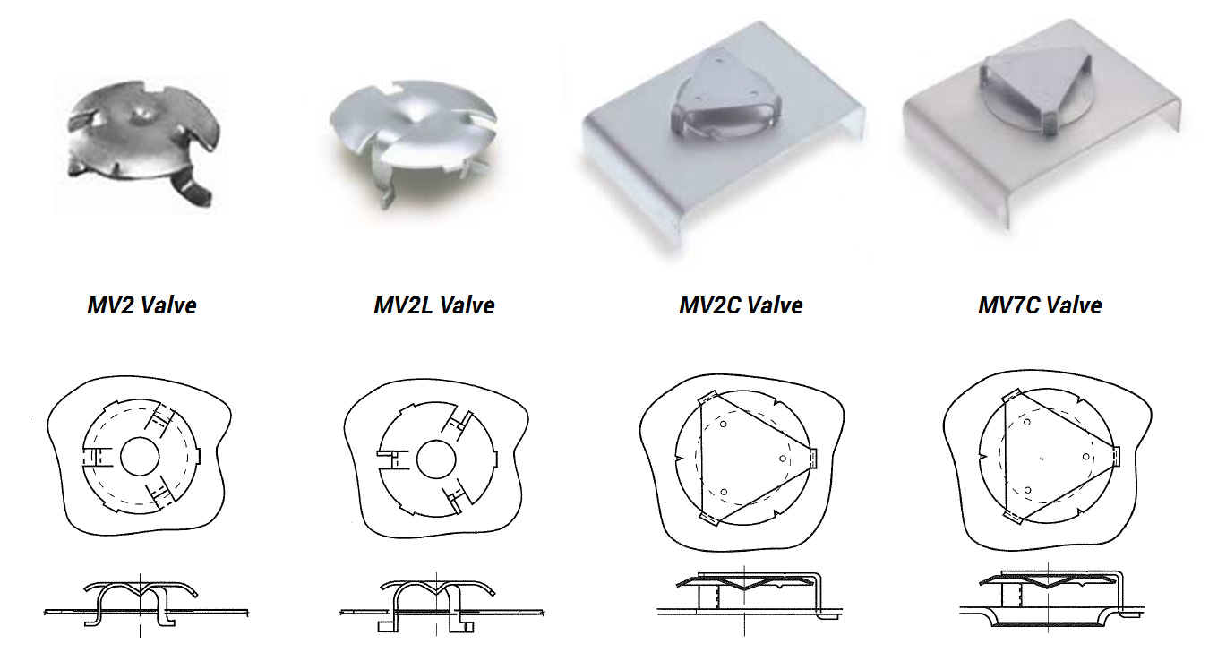
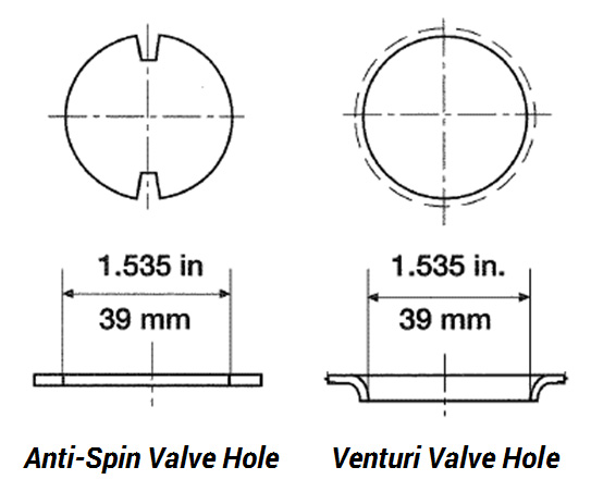
Other options :
• Anti-spin orifice tabs to prevent tray deck valve orifice and valve leg erosion.• Caged valves which are used with venturi-type deck openings for low pressure drop applications, or with plain deck openings where non-legged valves are beneficial. They are also appropriate for low liquid load applications or in certain types of corrosive environments
Various Tray Hydraulics
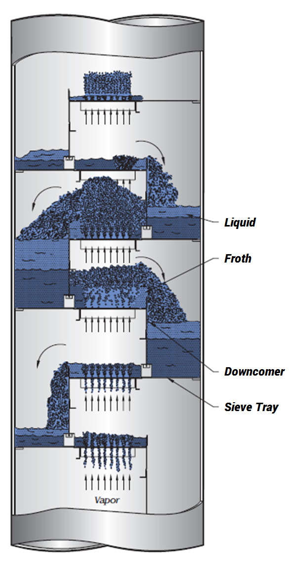
Blowing Tray
Tray floor visible, low delta P (low efficiency)Tray partially active
May Leak (some loss of efficiency)Tray at 85% flood
Beginning to Entrain (loss of efficiency)Tray at 80% flood
Optimum operation (peak of efficiency)Tray at weep point
Occasional weeping (efficiency still satisfactory)Tray at dump point
No liquid flow over weir (poor efficiency)